
02 RGB Led with ESP32
Introduction:
Here we are going to learn how to interface common cathode RGB Led with ESP32 by using Arduino IDE. We will use PWM pin for RGB Led because it require analog voltage to glow different color.
Components:
Common Cathode RGB Led ESP32
ESP32
Schematic Diagram: Let us code with Arduino IDE:

It is defined here Led pin and channel. Led Red, Green and Blue defined GPIO 25, 26 and 27. Channels are defined 0, 1 and 2 for Red, Green and Blue Leds. We use 5000 frequency and 8 bit PWM resolution.
 #define LEDR 25
 #define LEDG 26
 #define LEDB 27
 #define R_channel 0
 #define G_channel 1
 #define B_channel 2
 #define pwm_Frequency 5000
 #define pwm_resolution 8
This is void setup function. It will only one time. ledcAttachPin() function will connect Led Pin to channel. Here LEDR pin is connect to R_channel, LEDG pin is connect to G_channel and LEDB pin is connect to B_channel.
ledcSetup function initialize PWM output for Led pins and we passed channel name, pwm frequency and pwm resolution.
 void setup() {
  ledcAttachPin(LEDR, R_channel);
  ledcAttachPin(LEDG, G_channel);
  ledcAttachPin(LEDB, B_channel);
  ledcSetup(R_channel, pwm_Frequency, pwm_resolution);
  ledcSetup(G_channel, pwm_Frequency, pwm_resolution);
  ledcSetup(B_channel, pwm_Frequency, pwm_resolution);
 }
This is RGB_Color function. We have to pass RGB color code in decimal.
 void RGB_Color(int i, int j, int k)
 {
  ledcWrite(R_channel, i);
  ledcWrite(G_channel, j);
  ledcWrite(B_channel, k);
 }
This is void loop function. It runs infinite time. Here Led will glow with different color with 500 ms delay.
 void loop() {
  RGB_Color(255,0,0); // RED color
  delay(500);
  RGB_Color(0,255,0); // green color
  delay(500);
  RGB_Color(0,0,255); // blue color
  delay(500);
  RGB_Color(255,255,0); // yellow color
  delay(500);
  RGB_Color(0,255,255); // cyan color
   delay(500);
  RGB_Color(255,0,255); // magenta color
   delay(500);
  RGB_Color(255,20,147); // deep pink color
 }
Arduino Code
 #define LEDR 25 // RED pin of rgb led is connected to 25 gpio pin
 #define LEDG 26 // green pin is connected to 26 gpio
 #define LEDB 27 //
 #define R_channel 0
 #define G_channel 1
 #define B_channel 2
 #define pwm_Frequency 5000 // pwm frequency
 #define pwm_resolution 8 // 8 bit resolution
 void setup() {
  ledcAttachPin(LEDR, R_channel);
  ledcAttachPin(LEDG, G_channel);
  ledcAttachPin(LEDB, B_channel);
  ledcSetup(R_channel, pwm_Frequency, pwm_resolution);
  ledcSetup(G_channel, pwm_Frequency, pwm_resolution);
  ledcSetup(B_channel, pwm_Frequency, pwm_resolution);
 }
 void loop() {
  RGB_Color(255,0,0); // RED ccolor
  delay(500);
  RGB_Color(0,255,0); // green color
  delay(500);
  RGB_Color(0,0,255); // blue color
  delay(500);
  RGB_Color(255,255,0); // yellow color
  delay(500);
  RGB_Color(0,255,255); // cyan color
   delay(500);
  RGB_Color(255,0,255); // magenta color
   delay(500);
  RGB_Color(255,20,147); // deep pink color
 }
 void RGB_Color(int i, int j, int k)
 {
  ledcWrite(R_channel, i);
  ledcWrite(G_channel, j);
  ledcWrite(B_channel, k);
 }
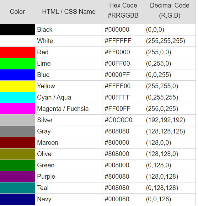
This is basic RGB Color code table. It will be helpful to know RGB color code
Thanks for visiting💖 🙏
Please Donate to help me and afford new equipment & components to make more videos and blogs.
Please Donate us


No comments: