
02 Set Configure bit of PIC controller
Configuration Bit:-
Configuration Bits are a collection of binary data located in the Flash program memory of a PIC microcontroller (MCU). Configuration bits are programmed into the PIC MCU with the application code. These bits are not executable code as their addresses are not accessible by the program counter. Configuration bits are derived from compiler directives placed into the code by the application developer.
Configuration bits are read by the MCU when exiting a reset and cannot be modified during run-time. Upon exiting reset, the configuration bits are used to complete circuitry which enables or disables hardware features of the MCU.
How to set the Configure Bits in MPLAB:-
MPLAB users can edit these configuration bits by using Configuration Bits tool.
In the top menu bar click Production>>Set Configuration Bits as shown down below
 Go to Configure bit then select bit as per your requirement.
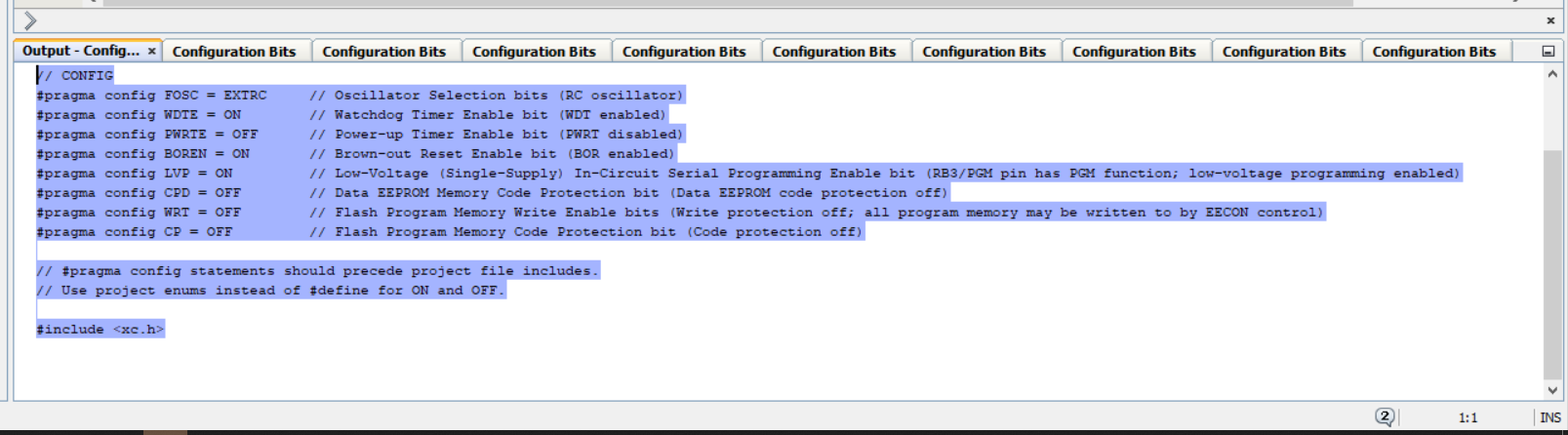
The features controlled by configuration bits are:
- Oscillator Selection Bits
- Watchdog Timer Enable Bits
- Power-up Timer Enable Bits
- Brown-out Reset Enable Bits
- Low-Voltage (Single-Supply)
- Data EEPROM Code Protection Bit
- Flash Program Memory Write Enable Bit
- Flash Program Memory Code Protection Bit
Oscillator Selection bits (FOSC):-
The Oscillator provides the clock signal for operation of controller. PIC Controller (PIC16F877A) can be operated in four different modes.
- LP Low Power Crystal
- XT Crystal/Resonator
- HS High Speed Crystal/Resonator
- RC Resistor/Capacitor
Watchdog Timer (WDT):-
Sometimes we can see the controller is not working properly then mostly we reset the controller by pressing of reset button but it is not good way to solve every times. To solve this thing we use watch dog timer. Watchdog time is an electronics timer which is integrated in microcontrollers and is used to detect and recover from above problem. it is simple counter that gives pulses to restart the microcontroller unit. The output of the watchdog timer is given directly to the micro controller reset signal. it is actually a free run counter where our program needs to write zero in every time it executes correctly.
Power-up Timer (PWRTE):-
The power-up timer introduces a small delay after power-up reset or brown-out reset. The quick start of the microcontroller after the rest can cause problems. The power-up timer provides a startup delay of 72 ms which allows VDD to rise to an acceptable level. The reset state of the chip is retained as long as the PWRT is active. The PWRTE is active. The PWRTE ensures the stability of the supply voltage before the clock gets started.
Brown-Out Reset (BOR):-
Low-Voltage (Single Supply):-
Data EEPROM Code Protection Bit (CPD):-
PIC16F877A has internal EEPROM data, CPD and WRTD, These protect the entire data of EEPROM from external Read and Write. CPD controls external and internal read and write and WRTD controls internal read and write.
Flash Program Memory Write Enable bit (WRT):-
These bits allow as to select the sectors in the flash programming memory for recording of the data or for the In-Circuit Serial Programming. We can write to the flash memory by the use of EECON. The firmware can be used to write data into the flash memory.
Flash Program Memory Code Protection bit (CP):-
Watch video for more details
Thanks for visiting🙏


No comments: